
Use of Ion Exchange Filters in Wastewater Treatment


Abstract
The authors describe the existing methods of electroplating wastewater treatment in industrial enterprises of the world, particularly in the engineering industry. In this paper, the authors address issues of modernization of the existing system of electroplating wastewater after treatment by the example of the machine-building enterprises through ion-exchange filters. The calculations are carried out on the example of applying cat ion and anion exchange filters. These filters allow one to change the ionic composition of the solution and to carry out its complete demineralization. They have a relatively high filtration rates, the possibility of fully automate systems and the possibility of regenerating ion exchangers, though impurities removed from water do not form a precipitate. The research has shown that the solution of merely technical challenges results in overloading and reducing the efficiency of wastewater treatment plants. Sustainable development could be achieved through the reorient a ting industrial processes of goods producing and services onto the new models, implementing environmentally friendly technologies for the creation of environmentally friendly production, ensuring a more efficient use of raw materials, replacing the most toxic electrolytes, systematic and irregular changing technological solutions and developing ways to recover waste solutions containing the same type of components.
Keywords: Electroplatingwastewater treatmention-exchange filtersengineering industry
Introduction
Electroplating is used in almost all industries. Electroplating is characterized by high prevalence, a considerable variety of processes, compositions of solutions and electrolytes, the formation of sufficiently toxic waste of various compositions. The main set of electrolytes and technological solutions can be considered as prevailing and is unlikely to radically change in the near future, which would have caused a sudden jump in the development of electroplating. On the other hand, the development of technology and equipment for processing of electroplating wastes is currently being implemented rapidly (Tashchiyan et al., 2015; Nikitin et al., 2016). Despite the significant differences in the technology of metal coatings of various products, electroplating production is one of the most dangerous sources of pollution, mainly surface and underground waters, due to the formation of a large amount of wastewater containing contaminants of heavy metals, inorganic acids and alkalis, surfactants substances (SAS), and other highly toxic compounds. In addition, with the introduction of new manufacture facilities, there emerged difficulties in cleaning and marketing wastewater at plants in China, Algeria, Iran, Turkey, India and Russia. The main supplier of toxic substances in the electroplating industry and the main source of wastewater are washings. The volume of waste water is very high due to the imperfect method of washing the components, which requires a large flow rate (up to 2 m3 or more per 1 m2 of detail surface). Annually, the items washing takes out of the working baths at least 3300 tons of zinc, 2400 tons of nickel, 2500 tons of copper, tens of thousands of tons of other metals, including heavy metals, acids and alkalis (Trifonov et al., 2014).
The sources of pollution in electroplating are not just washings and waste concentrated solutions. Failure of working solutions occurs due to the accumulation of organic and inorganic substances in extraneous electrolytes and irregularity of the ratio of the main components in the electroplating baths. Emissions of waste solutions make up 0.2-0.3% of the total amount of waste water in terms of volume and up to 70% in terms of the total content of discharged pollutants.
Entering of untreated or inadequately treated wastewater and other waste containing non-ferrous and heavy metals into water objects causes damage to the environment due to their huge negative environmental impact. Ecological problems of electroplating attract extensive attention largely because of the continuing environmental pollution with heavy metal ions (Shabashev et al., 2014; Babikova et al., 2011). Metal compounds which are taken out with electroplating production wastewater adversely affect the ecosystem of a pond - soil - a plant - animal world - a man. Chromium compounds (Vl) exert general toxic, irritant, cumulative, allergenic, carcinogenic and mutagenic effects on any living organism, as well as detrimentally influence the flora and fauna of the ponds in general and thereby hinder the processes of self-purification.
Wastewater Treatment Process is organized in order to use it in systems of circulating, sequential or closed water supply, to ensure reception conditions in the urban systems of drainage or discharge into the water objects. Sewage treatment facilities were launched before the 1990s in many engineering companies; in this regard, the choice of equipment of satisfactory performance and cleaning efficiency is essential for purification of wastewater as a complete replacement of the existing equipment is not possible due to the necessity of large capital investments (Lizunkov et al., 2016). But so far, there has not been any universal purification equipment capable to neutralize the whole range (in composition and volume) of electroplating waste. Therefore, purification equipment is used with a significant margin both in performance and versatility that comes in conflict with the economic possibilities of plants. In today's market economy production flexibility and making profit are coming to the fore instead of production monotony and rhythm, production at all costs or just survival, thus requiring increased flexibility and performance of purification equipment becomes increasingly strengthened (Suzdalova et al., 2015).
Problem statement and objectives of the research
Separate and sometimes independent development of applied electroplating and environmental protection often leads to industrial conflicts among experts of these kinds of technologies which further aggravates the unfavorable ecological situation (Kindaev, & Moiseev, 2016; Suzdalova, & Kvashnina, 2015). The main objectives of electroplating are to improve processes performance, cost reduction and the achievement of the required product quality. In the majority of cases, the solution of these problems apart leads to congestion and reduction of the sewage treatment plants efficiency, an increase of charges for environmental pollution and ultimately to an increase in production costs.
Methods. Findings on ion exchange water treatment technique
For further post-treatment of wastewater, a variety of physical and chemical methods can be used based on adsorption and ion exchange. But one of the most effective modern methods of natural and waste water treatment is associated with the use of ion exchange. This method allows one to clean the water to the maximum admissible concentration of harmful substances, dispose toxic components and use purified water not only for re-production purposes, but also for drinking needs (Lizunkov et al., 2015; Lizunkov et al., 2016). An ion exchange method can be used to extract substances from solutions practically at any concentration including very low ones and the cases when other methods are ineffective. Ion exchangers make it also possible to change the ionic composition of the solution, to carry out its full demineralization in water treatment.
The ion exchange water treatment method advantageously differs by the fact that it does not require a continuous dosing of reactants and impurities removed from water do not form a precipitate (Suzdalova et al., 2015). The purification process comes to the water passage through the sorbent bed. The relatively high rate of filtration allows reducing the dimensions of the devices. The advantages of ion exchangers include the ability to fully automate systems and regenerate stuff that allow the use of ion exchangers in multiple recurrent filtration cycle. The post-treatment cycle using ion exchangers can be clearly demonstrated in Figure
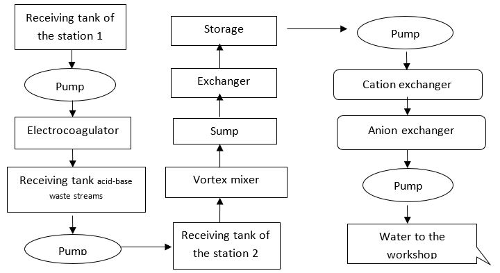
For the mechanical engineering industry, we suggest the use of ion-exchange columns which would be appropriate to place following tanks - storage of purified water. In order to have ion-exchange column working properly, it is necessary to calculate the load on ion exchange filters, reagent consumption for advanced treatment and regeneration, as well as water consumption. There are usually 3 filters installed there: 2 operating and 1 held in reserve.
Calculation of ion exchange filters
The ion exchange unit receives neutralized and clarified effluent with residual heavy metal cation content of no more than 0,3g•eq/m3. As a result of ion exchange, demineralization of 20% of water supplied to manufacturing its salt composition is stabilized. The cations and anions are desorbed from the ion exchangers with acid and alkaline solutions.
The acid reagents, obtained through the ion exchange, undergo reactant treatment and are discharged into the soil system, which means they are neutralized by alkalis according to the equation:
(1)
Alkaline reagents are discharged into the receiving tank of electrolytes and then dosed into the general industrial flow to a vortex mixer. The process of ion exchange water treatment concerns: pumping water for ion exchange purification, ion-exchange filters (cation and anion) for water demineralization, preparing and serving regeneration solutions, purifying acid eluates (acids used for regenerating the cation).
Filtration rate
(2)
where Q is number of waste, and
Working filter capacity is calculated as follows:
,(3)
where
The working cycle is determined according to the formula:
,(4)
where Y is a load filter volume, n – the number of working filters.
Calculation of indicators of reagents consumption for ion exchanger regeneration is made in accordance with the technological performance of certain ion exchanger type. Consumption of 100% reagents for regeneration of one filter is calculated according to the formula:
,(5)
where В is a relative reagents consumption.
From the ion exchangers, the reclaimed product comes, the volume of which is equal to:
,(6)
where Cr is the concentration of regenerating solution.
Technological scheme of effluent aftertreatment on ion-exchange stands
Waste water from the intermediate storage vessels are supplied initially to the cation and then to the anion filter with the help of pumps. In this process, resins lose their ability to exchange ions, thus the treatment quality is gradually deteriorating. The operating cycle on cation filter ends at breakthrough of heavy metal ions and Na+ ions into the filtrate and on anion filter - at breakthrough of Cl- ions.
To restore the exchange capacity of ion exchange resins, filter regeneration is carried out and includes resin backwashing, regenerating and afterregeneration washing (Nesteruk & Momot, 2014). After disconnecting the filter, waste water is dumped into the drain pipe from there, discharging effluents into a receiving tank of the sewage pumping station. Then the ion exchanger is loosened with countercurrent water supplied from the industrial water pipe network and is also discharged into the drain pipe. Then the cation exchanger is regenerated with 1N H2SO4 solution which is pumped from a tank. Deacidifying is being carried out with industrial water for 60 minutes at 10m3/hr. The washings are then discharged back into the drain pipe. The anion exchanger is regenerated with 1N NaOH solution which is pumped from another tank. Then it undergoes alkali removing for 2h. 30 min. with industrial water which is later dumped in a drain pipe.
Results. Using cation and anion exchange filters
Calculation of cation filters
For the initial data, we accept the following obtained figures: number of waste (Q) entering the filters is equal to 40 m3/h; the total content of cations - 0.54
; Na+ ions - 0,54
. For ion exchange treatment, we use cationic filter HV-042-1 which properties are presented in Table
In this case, the rate can be calculated according to equation (2) and is equal to
The working cycle is determined according to formula (4), where Y is equal to 3.56 m3. Thus we get
Consumption of reagents for cation exchangers regeneration
Calculation of indicators is made in accordance with the technological performance of cation exchanger and with formula (5), where B is 100 g/eq•r, as follows:
The concentration of regenerating acid solution Cr is 1.2 kg•eq/m3. From cation filter there comes the reclaimed product, the volume of which is equal to (6):
Cation exchanger loosening is made with purified water with an intensity of 3 l/s•m2. Thus, the water flow rate per filter amounts to 3 * 1.6 = 4.8 l/s or 17.28 m3/hr at loosening continuation for 15 minutes or 0.25 hours. The amount of water per filter will be 17.28 * 0.25 = 4.32 m3. Afterregeneration rinsing consumes 5 volumes of water per 1 m3 of the resin, then:
The duration of rinsing in this process amounts to 60 minutes, and the total water consumption per one filter is 8 = 4.32 + 12.32 m3/day. Loosening and rinsing of filters are carried out with purified water from the industrial pipeline.
Calculation of anion filters
The number of waste (Q) entering the anion filters is equal to 40 m3/h; the total content of anion - 0.5 g•eq/m3. For ion exchange treatment, we use anion filter HV-040-1 which properties are presented in Table
In this case, the rate can be calculated according to equation (2) and is equal to
The working cycle is determined according to formula (4), where Y is equal to 1.6 m3,
- 0.5 g•eq/l. Thus we get
Consumption of reagents for anion exchangers regeneration
Calculation of indicators is made in accordance with the technological performance of anion exchanger and with formula (5), where B is 40 g/eq•r, as follows: = 1.6*425*40/1000=28.8 kg.
The concentration of regenerating alkali solution Cr is 1.2 kg•eq/m3. From the anion filter, there comes the reclaimed product, the volume of which is equal to (6):
The anion exchanger loosening is made with industrial water with an intensity of 2 l/s•m2. Thus, the water flow rate per 1 filter amounts to 2 * 0.8 = 1.6 l/s or 5.76 m3/hr at loosening continuation for 20 minutes or 0.33 hours. The amount of water per 1 filter will be 5.76 * 0.33 = 1.9 m3. Afterregeneration rinsing consumes 15 volumes of water per 1 m3 of the resin, then:
Duration of one filter rinsing in this process amounts to 2 hours and the total water consumption is 1.90+24=25.9 m3/day.
Conclusion
In the majority of cases, the solution of merely technical challenges (an increase in productivity of processes, cost reduction and achievement of the required product quality) results in overloading and reducing the efficiency of wastewater treatment plants. Achieving sustainable development is possible only through the reorientation of industrial processes of goods producing and services onto the new models which will assist in reducing the environmental load and increasing efficiency of industrial production (Lizunkov, Minin, Malushko & Medvedev, 2016). It is necessary to implement environmentally friendly technologies for the creation of environmentally friendly production preventing nature pollution and ensuring a more efficient use of raw materials.
In order to reduce ecological hazard of electroplating, it is necessary to replace the most toxic electrolytes. Replacing the chromium plating electrolytes based on he avalent chromium compounds is facing an acute problem. Its pendency required the development of chromium plating electrolytes based on trivalent chromium compounds which would replace electrolytes based on hexavalent chromium compounds at least in some cases.
Unsystematic and irregular change of technological solutions as well as their high environmental danger demanded improvement and simplification of electrolyte purification procedures from contamination, determination of technological solutions lifetime and development of ways to recover waste solutions containing the same type of components.
Acknowledgements
We are grateful to the Institute of Philology and Intercultural Communication at Volgograd State University and the Department of Economics and Automated Control Systems at Yurga Technological Institute (branch) of Tomsk Polytechnic University for the research opportunity and assistance. We are also grateful to the staff of workshop #44 at "Yurga Machine Building Plant" LLC for the information and materials necessary for the study of electroplating and calculation.
References
- Babikova, А.V., Fedotova, А.Yu. & Shevchenko, I.К. (2011). Problemy i perspektivy razvitija inzhenernogo obrazovanija v innovacionnoj jekonomike [Problems and future prospects of engineering education in innovation-oriented economy]. Engineering Journal of Don, 16 (6), 195-204.
- Kindaev, A.Yu. & Moiseev, A.V. (2016). Problems of interaction between insurance companies and farmers. [Problemy vzaimodeystviya strakhovoi kompanii s selskokhosyaistvennymi organizatsiyami.] Vestnik of Samara State University for Economics, 5(139), 72-76.
- Lizunkov, V. G., Marchuk, V. I. & Podzorova, E. A. (2015). Identification of Criteria, Features and Levels of Economic and Managerial Competencies Development for Bachelors in Mechanical Engineering. Procedia - Social and Behavioral Sciences, 2015, Vol. 206, 388-393.
- Lizunkov, V. G., Minin, M. G., Malushko, E. Y. & Medvedev, V. E. (2016). Developing economic and managerial competencies of bachelors in mechanical engineering. SHS Web of Conferences, № 28, 01063, URL: http://www.shs-conferences.org/articles/shsconf/abs/2016/06/shsconf_rptss2016_01063/shsconf_rptss2016_01063.html (date of access: 18.06.2016).
- Nesteruk, D.N. & Momot, M.V. (2014). Information Technology of Estimation and Forecasting Innovative Activity Based on Distributed Data Input. Applied Mechanics and Materials, Vol. 682, 579-585.
- Nikitin, A.A., Paljyanov, M.P., Morozova, M.V. & Markovichev, A.S. (2016). The Management of Advanced Training of Engineering and Technical Specialists Based on the Interaction between Universities and Business-Structures. International Review of Management and Marketing, 6 (1), 75-80.
- Shabashev, V.A., Trifonov, V.A. & Verzhitsky, D.G. (2014). The problems of developing the ecological market of the region. Applied Mechanics and Materials, Vol. 682, 591-595
- Suzdalova, M.A. & Kvashnina, D.A. (2015). Potential of IT culture as a means of development of high-tech educational IT environment. BULLETIN, Buryat State University, 14A, 190-192.
- Suzdalova, M.A., Politsinskaya, E.V. & Sushko, A.V. (2015). About the problem of professional personnel shortage in mechanical engineering industry and ways of solving. Procedia - Social and Behavioral Sciences, Vol. 206, 394-398.
- Suzdalova, M.A., Politsinskaya, E.V. & Sushko, A.V. (2015). On problem of professional personnel shortage in engineering industry and its solution. Procedia - Social and Behavioral Sciences, 206, 394-398.
- Tashchiyan, G.O., Sushko, A.V. & Grichin, S.V. (2015). Microsoft Business Solutions-Axapta as a basis for automated monitoring of high technology products competitiveness. IOP Conference Series: Materials Science and Engineering, Vol. 91, Article number 012065, 1-6.
- Trifonov, V.A., Grichin, S.V. & Kovaleva, M.A. (2014). Price differentiation as economic and mathematical model of increasing the competitive power of a company. Applied Mechanics and Materials, Vol. 682, 606-612.
Copyright information

This work is licensed under a Creative Commons Attribution-NonCommercial-NoDerivatives 4.0 International License.
About this article
Publication Date
20 July 2017
Article Doi
eBook ISBN
978-1-80296-025-9
Publisher
Future Academy
Volume
26
Print ISBN (optional)
Edition Number
1st Edition
Pages
1-1055
Subjects
Business, public relations, innovation, competition
Cite this article as:
Ergunova, O., Ferreira, R., Ignatenko, A., Lizunkov, V., & Malushko, E. (2017). Use of Ion Exchange Filters in Wastewater Treatment. In K. Anna Yurevna, A. Igor Borisovich, W. Martin de Jong, & M. Nikita Vladimirovich (Eds.), Responsible Research and Innovation, vol 26. European Proceedings of Social and Behavioural Sciences (pp. 541-549). Future Academy. https://doi.org/10.15405/epsbs.2017.07.02.69